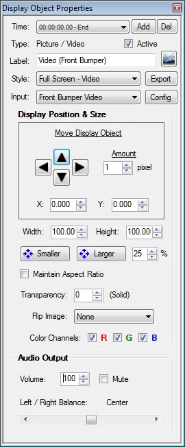
This properties box can be displayed by clicking the Properties button under Display Objects on the Main screen, by double-clicking a display object in the main preview, or from the Timeline View.
The controls and options will vary depending on the type of display object selected. You can view more information about most controls by placing the mouse pointer over it for a few seconds, which will display its tool-tip text. Certain items may be grayed-out and disabled in editions that do not support the corresponding feature.
See Also:
Timeline
Gauge Designer
Enhanced Object Script Editor
Common Controls in the Display Object Properties box
- Time - Selects the timeline instance that you are editing for this the display object. Changes made to the display object's properties will apply to the current timeline segment, and any following segments until additional changes are made. Clicking on the "Time:" label will open the Timeline Segment Editor, where you can change the segment's start time and select which parameters are altered in this segment.
- Add - Creates a new timeline segment at the project time of your choosing. Changes made at that point will then only apply to the project from that point forward.
- Del - Removes the current timeline segment and any changes that had been made during it.
- Active - Controls whether this display object is currently used in the project or not.
- Label - Displays or edits the name of this display object to show in the list on the Main screen and all other display object lists.
- Image Icon - Opens the Background Image screen, which allows you to import an image file to use for this object's background. This can be used to make the object have a realistic or custom gauge face.
- Style - Import or export a Display Object Style file. Selecting a file will override all current settings with those of the selected file. If you create a display object configuration that you want to share with other RaceRender 2 users, or another computer, use the Export button to save the current display object into a file.
- Input - Select the Input File to use for this display object.
- Config - Open the Input File Configuration screen.
- Display Position & Size
- Move Display Object - Click or hold the arrows to move this display object around the screen. You may also directly click & drag it on the Main screen.
- Amount - Set the number of pixels for each movement when using the arrows. A smaller number allows more precision, but a slower movement speed.
- X & Y - Current coordinates of the display object's lower left corner. These are represented as percentages of the screen's total width and height.
- Width & Height - Current relative size of the display object. These are represented as percentages of the screen's total width and height.
- Smaller & Larger - Shrinks or expands the display object by the percentage in the number box. This will not change the font size of Text-based display objects; you will need to adjust that separately.
- Maintain Aspect Ratio - Enforces the proper aspect ratio of the display object,
reducing its displayed size if necessary. The actual object size will remain unchanged,
but may include unused space, depending on the aspect ratios of the object and the
screen. For video or picture objects, this can result in a letterbox effect, except that
the unused area will be transparent instead of always being black. Remember to set the
preview screen to the same aspect ratio that you intend
to use in your output video file, so that the preview is a more accurate representation.
- Transparency - Sets the transparency effect percentage. 0% is completely solid; 100% is completely transparent (invisible). Setting this to a high number can be useful for creating watermarks.
- Mirroring - Flips the output image horizontally, vertically, or both.
- Color Channels - Controls which RGB color channels are drawn. This is typically only used for creating 3D anaglyphs, but might also be useful for other effects. Disabled color channels will be transparent, sometimes causing an opposite effect. For example, if only the red channel is enabled, then the red from this display object will replace the red channel of any object drawn beneath it, but that objects's blue and green channels will remain. The result is both object images being ghosted together. It can also be used to create a tint, if there is no other object drawn beneath it, or there is a black underneath. For tints, you may also want to set input file's Color to 0%.
- Audio Output
- Volume - Adjust the output audio level for this display object from 0% to 200%. Checking the Mute box has the same effect as setting it to 0%.
- Left / Right - Control how much of this display object's audio comes out of each speaker. Setting this towards the left would make it sound like its coming more from the left side than the right.